
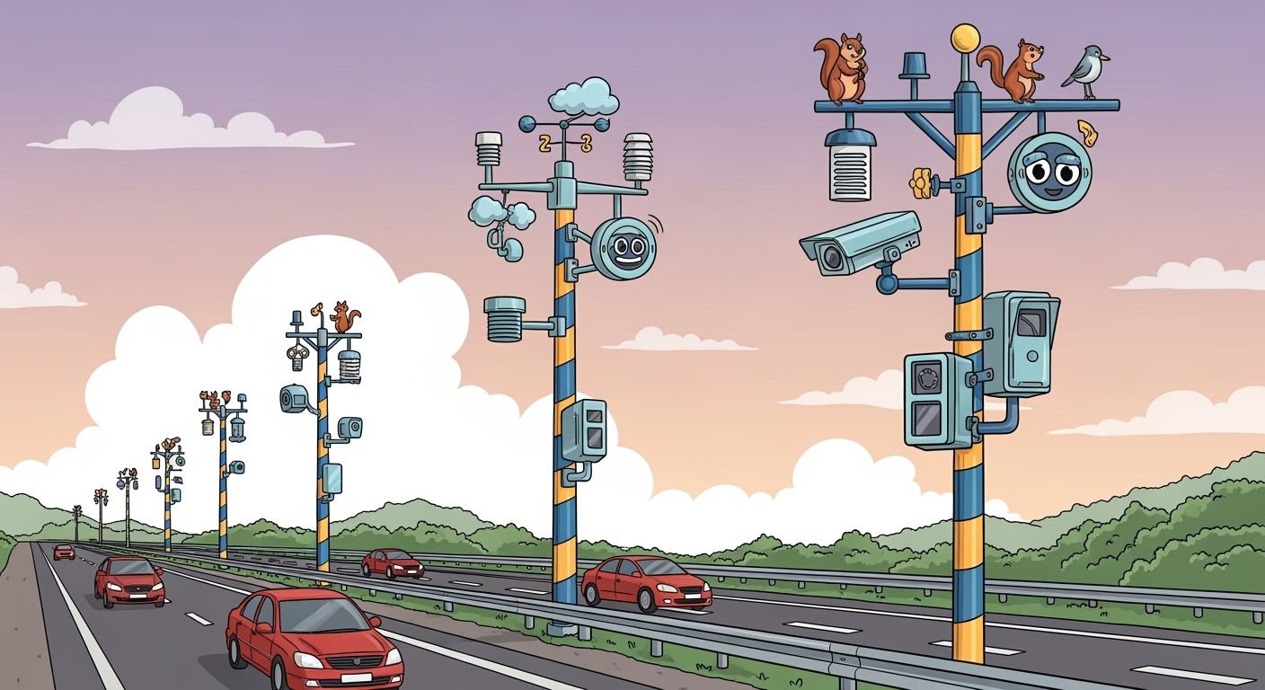
Roadside ITS poles provide stable mounting infrastructure for weather sensors, traffic cameras, radar units, communication equipment, and other intelligent transportation system components. Transportation authorities, engineering contractors, and system integrators use these poles to collect real-time information about traffic flow, visibility, precipitation, road surface conditions, and other environmental risks.
Unlike standard lighting poles, ITS poles must accommodate additional equipment loads, cable routing, access panels, power supplies, communication modules, and site-specific wind conditions. Some projects also combine ITS equipment with smart poles or roadway lighting to reduce the number of separate structures and simplify infrastructure management.
Successful deployment requires coordinated structural engineering, sensor placement, foundation design, corrosion protection, and maintenance access. LeapPole provides configurable pole and mounting solutions for roadside monitoring, traffic management, and outdoor lighting projects.
Key Takeaways
- Define the monitoring objective before selecting the pole, sensors, cameras, brackets, and communication equipment.
- Evaluate roadway geometry, precipitation, terrain, microclimates, wind load, soil conditions, and equipment exposure during the site assessment.
- Integrate ITS equipment with road traffic facilities or street lighting where combined infrastructure can reduce installation and maintenance requirements.
- Calculate the total equipment weight and effective projected area instead of selecting a pole based only on height.
- Plan internal cable routing, access doors, grounding, surge protection, power supply, and communication connections before fabrication.
- Select sensor technologies according to the required accuracy, detection range, environmental rating, communication protocol, and maintenance strategy.
- Confirm compliance with local roadway clearance, structural, electrical, traffic management, and data security requirements.
- Use modular mounting provisions to support future cameras, sensors, 5G equipment, edge computing devices, and other ITS upgrades.
Part1: Roadside ITS Pole Applications1.1 Road Weather Monitoring
Road weather monitoring systems collect localized environmental information that may not be available from regional weather stations. Typical devices include:
- Air temperature and humidity sensors
- Precipitation sensors
- Visibility and fog detectors
- Wind speed and direction sensors
- Pavement temperature sensors
- Road surface condition sensors
- Water-level or flood monitoring devices
The number and location of monitoring points should reflect the roadway environment. Mountain passes, bridges, shaded sections, flood-prone roads, coastal corridors, and areas affected by fog or icing may require targeted monitoring.
High annual precipitation alone does not determine pole spacing. Engineers should also consider elevation changes, exposure, maintenance practices, known accident locations, and local microclimates. The Federal Highway Administration provides guidance on road weather management and the use of environmental information in traffic operations.
1.2 Traffic and Incident Detection
ITS poles can support cameras and traffic detectors used to monitor:
- Vehicle volume and speed
- Lane occupancy
- Queues and congestion
- Wrong-way movement
- Stopped vehicles
- Pedestrian and cyclist activity
- Incidents and roadway obstructions
Equipment selection depends on the detection objective. A camera intended for general traffic observation has different mounting and optical requirements from a camera used for vehicle identification or incident analysis.
The pole should provide sufficient rigidity to limit image movement while also allowing technicians to reach cameras, junction boxes, and communication devices safely.
1.3 Intersections and Functional Zones
Each roadway zone has different monitoring requirements.
At intersections, ITS equipment may support signal control, vehicle detection, pedestrian monitoring, and incident verification. Highway ramps may require speed detection, queue monitoring, and coverage of merging areas. Bridges and tunnels may need weather, visibility, structural, and traffic monitoring.
School zones, hospitals, border checkpoints, tolling areas, and freight corridors can require additional devices or specialized mounting arrangements.
ITS poles should therefore be configured for the functional zone rather than selected from a single standard specification. LeapPole’s road traffic facilities can be configured for traffic signals, signs, cameras, sensors, and related roadway equipment.
1.4 Integration with Roadway Lighting
Combining ITS equipment with street lighting can reduce the number of foundations and roadside structures. A shared pole may support:
- LED roadway luminaires
- Traffic cameras
- Weather sensors
- Radar units
- Wireless communication devices
- Equipment cabinets
- Emergency communication devices
Integration does not automatically mean that all devices can use the same electrical circuit or communication network. Lighting, monitoring, and communication systems may have different voltage, grounding, cybersecurity, and maintenance requirements.
Engineers must verify the additional mechanical loads, cable space, access requirements, and electrical separation before integrating ITS devices with street light poles.
Part2: Sensors, Cameras, and Communication Equipment
2.1 Weather and Pavement Sensors
Weather sensors should be selected according to the measurement objective and environmental conditions.
Air temperature and humidity sensors require adequate airflow and protection from direct heat sources. Visibility sensors need a clear measurement path. Wind sensors should be positioned away from large obstructions that could distort airflow.
Road surface sensors may be installed in the pavement or use non-contact measurement technologies mounted beside or above the road. Embedded sensors can provide direct pavement data but require roadwork for installation and replacement. Non-contact sensors simplify maintenance but must have the correct viewing angle and distance.
Sensor accuracy, calibration requirements, environmental rating, communication interface, and replacement procedure should be reviewed during procurement.
2.2 Traffic Detection Technologies
Different traffic detection technologies offer different capabilities.
| Technology | Typical Strengths | Important Considerations |
|---|---|---|
| Camera-based detection | Vehicle classification, pedestrian detection, incident verification | Lighting, glare, privacy, bandwidth, and processing requirements |
| Radar | Long detection range and performance in poor weather | Mounting angle, interference, object classification, and coverage limits |
| LiDAR | Detailed distance measurement and three-dimensional data | Cost, processing requirements, installation complexity, and environmental exposure |
| Infrared sensors | Detection in low-light environments | Range, environmental interference, and maintenance |
| Inductive loops | Established vehicle detection technology | Pavement cutting, traffic disruption, and road-surface maintenance |
No single technology is suitable for every project. Engineers should select the technology according to detection range, classification requirements, weather conditions, installation constraints, and lifecycle cost.
Multiple technologies may be combined when the project requires detection redundancy or improved accuracy.
2.3 Camera Coverage and Placement
Camera placement should be determined through a coverage study rather than a fixed spacing rule. The study should consider:
- Required detection, recognition, or identification level
- Camera focal length and sensor resolution
- Pole height and mounting angle
- Horizontal and vertical field of view
- Road curves and elevation changes
- Large-vehicle occlusion
- Signs, trees, buildings, and future obstructions
- Daytime and nighttime lighting
- Headlight glare and backlighting
- Maintenance access
Higher mounting positions may improve overall coverage but reduce image detail. Lower positions may provide better identification while increasing the risk of obstruction or vandalism.
When cameras share poles with LED street lights, the luminaire position and optical distribution should be coordinated to prevent glare or excessive contrast in the camera image.
2.4 Data Transmission and Edge Processing
Roadside equipment may communicate through fiber-optic cable, Ethernet, cellular networks, licensed radio, Wi-Fi, or other wireless systems. The correct method depends on bandwidth, latency, cybersecurity, coverage, and infrastructure availability.
A typical system can include:
| Component | Function |
| Sensors and cameras | Collect traffic and environmental information |
| Data acquisition unit | Receives and organizes sensor signals |
| Edge processor | Performs local filtering, detection, or analysis |
| Communication equipment | Transfers information to a control platform |
| Central monitoring platform | Displays data, generates alerts, and stores records |
| Power and backup system | Maintains operation during normal and emergency conditions |
Edge processing can reduce the amount of data transmitted to the central platform. It may also support faster incident alerts when network bandwidth is limited.
Cabinets and access doors should provide adequate space, heat management, ingress protection, cable organization, and maintenance clearance.
Part3: ITS Pole Engineering and Configuration
3.1 Structural Load Assessment
ITS pole design should be based on the complete installed equipment configuration. Engineers must consider:
- Pole self-weight
- Cameras and sensor weights
- Luminaire and bracket loads
- Antennas and solar modules
- Equipment cabinets
- Effective projected area
- Local wind speed and terrain category
- Ice or snow loads where applicable
- Vibration and fatigue
- Equipment eccentricity
- Future reserved loads
Adding a small device can produce a significant structural effect when it is mounted high on the pole or far from the pole centerline.
Pole height alone is not enough to determine structural capacity. Project drawings should identify the location, dimensions, weight, and mounting height of every device.
3.2 Pole Material and Corrosion Protection
Steel is commonly used for ITS poles because it provides high structural strength and supports custom fabrication. Aluminum offers corrosion resistance and lower weight but requires careful evaluation of structural capacity and fatigue. Composite materials may be appropriate for selected environments but are not automatically suitable for every extreme-weather application.
Material selection should consider:
- Structural requirements
- Coastal or industrial exposure
- Maintenance resources
- Transportation and erection methods
- Electrical grounding
- Expected service life
- Local specifications
Steel poles may use hot-dip galvanizing, powder coating, or a duplex coating system. All welding, drilling, access openings, and mounting provisions should be completed before final galvanizing whenever the specified manufacturing process requires it.
3.3 Device Mounting and Access
Mounting arrangements can include:
- Top-mounted sensor brackets
- Side-mounted camera arms
- Adjustable equipment plates
- Pole-top solar structures
- External cabinets
- Internal equipment compartments
- Hinged or lowering mechanisms
Brackets should prevent unintended rotation and provide sufficient stiffness for the installed device. Mounting holes and interfaces should be coordinated with equipment suppliers before fabrication.
Access doors must not weaken the pole beyond the allowable structural limits. Door size, reinforcement, locking method, internal terminal boards, and maintenance clearance should be included in the engineering review.
3.4 Cable Routing, Grounding, and Surge Protection
Internal cable routing protects conductors from weather, vandalism, and accidental damage. Pole designs should include:
- Separate routes where power and data cables require segregation
- Smooth cable entry points
- Bushings or protective sleeves
- Pulling access
- Drainage and condensation management
- Grounding provisions
- Surge protection coordination
- Sealed cable exits
Cables should not rub against sharp edges or block access to electrical components. The grounding and surge protection strategy should account for the pole, equipment cabinet, power supply, communication equipment, cameras, sensors, and luminaires.
3.5 Grid, Solar, and Backup Power
Grid power is normally suitable where reliable electrical infrastructure is available. Remote sites may use solar power, battery backup, or hybrid systems.
A solar power system must be sized according to:
- Actual device consumption
- Operating schedule
- Communication equipment load
- Peak and standby power
- Local worst-case solar conditions
- Required autonomy
- Battery temperature range
- Panel orientation and shading
- Power losses
- Future expansion
Fixed “200 W to 800 W” packages should not be selected without a project energy calculation. Cameras, heaters, radar units, edge computers, and communication devices can create substantially different load profiles.
Part4: Installation, Standards, and Maintenance
4.1 Site and Utility Assessment
A site assessment should confirm:
- Road geometry and clear zones
- Soil conditions and drainage
- Underground and overhead utilities
- Installation access
- Traffic control requirements
- Flood risk
- Environmental restrictions
- Equipment line of sight
- Solar exposure where applicable
- Power and communication routes
- Permit requirements
The assessment should also identify future vegetation, planned road widening, new signs, and structures that could obstruct cameras or sensors.
4.2 Foundation and Anchor Design
Foundation dimensions should be determined from pole loads, soil properties, overturning moment, local structural requirements, and drainage conditions. A foundation copied from another project may not be suitable even when the poles have similar heights.
Anchor-bolt templates, base-plate dimensions, conduit locations, leveling provisions, and reinforcement details should be coordinated before foundation construction.
Direct-burial, anchor-base, surface-mounted, or specialized foundation systems may be used depending on the project. The final design should be confirmed by qualified local engineers.
4.3 Standards and Roadside Safety
Applicable standards depend on the country, road authority, pole function, and project specification.
Structural supports may need to follow relevant AASHTO requirements in North American projects or applicable EN and national standards in European projects. EN 12767 applies where passive-safety performance for roadside support structures is specified. It should not be treated as a universal wind-load requirement.
Other requirements may address:
- Structural loading
- Electrical safety
- Ingress protection
- Electromagnetic compatibility
- Grounding and surge protection
- Roadside clearances
- Camera and data systems
- Traffic control
- Product conformity
- Cybersecurity
Project teams should confirm the governing standards with the road authority and engineering consultant before procurement.
4.4 Inspection and Maintenance Planning
ITS poles require more than routine surface inspection. A maintenance plan should cover:
- Pole alignment and visible deformation
- Foundation settlement and cracking
- Anchor bolts and fasteners
- Corrosion and coating damage
- Brackets and mounting hardware
- Access doors and locks
- Cable seals and drainage
- Grounding and surge protection
- Camera alignment and image quality
- Sensor calibration
- Cabinet ventilation
- Solar panels and batteries
- Communication performance
Inspection frequency depends on the environment, equipment type, traffic exposure, manufacturer recommendations, and local requirements. Additional inspections may be required after collisions, severe storms, flooding, or construction work near the pole.
Maintenance personnel should have safe access to all devices without unnecessarily disrupting traffic.
Part5: Procurement and Future Readiness
5.1 Information Required for Quotation
A useful ITS pole quotation should be based on complete project information. Buyers should provide:
- Project location
- Pole quantity
- Required pole height
- Site layout or roadway drawings
- Basic wind speed and structural standard
- Soil or foundation information
- Equipment list
- Device dimensions and weights
- Mounting heights and orientations
- Power requirements
- Communication requirements
- Material and surface treatment
- Required drawings and calculations
- Inspection and test requirements
- Packing and delivery destination
Without this information, suppliers may quote different structural and commercial scopes, making direct price comparison unreliable.
5.2 Procurement Checklist
| Procurement Item | What to Confirm |
| Pole material | Grade, dimensions, wall thickness, fabrication method |
| Structural capacity | Wind load, equipment loads, EPA, fatigue, reserved capacity |
| Surface protection | Galvanizing, coating system, color, corrosion environment |
| Mounting provisions | Brackets, holes, interfaces, adjustment range |
| Access and cabling | Door size, cable routes, terminal space, sealing |
| Electrical provisions | Grounding, surge protection, power separation |
| Documentation | Drawings, calculations, material certificates, inspection reports |
| Logistics | Packing method, container loading, delivery scope |
| Support | Installation guidance, spare parts, warranty, engineering coordination |
5.3 Privacy and Cybersecurity
Camera and sensor deployments may collect sensitive operational or personal information. Project owners should establish policies for:
- Data minimization
- Encryption during transmission and storage
- User access control
- Password and credential management
- Software and firmware updates
- Network segmentation
- Data retention
- Incident response
- Public notification where required
Cybersecurity requirements should be included during system design rather than added after installation. Guidance from organizations such as NIST can support the development of appropriate cybersecurity controls.
Pole manufacturers are typically responsible for the physical infrastructure, but structural, electrical, communication, and cybersecurity teams should coordinate their requirements before fabrication.
5.4 Modular Expansion
ITS projects often expand after initial installation. Additional devices may include:
- Higher-resolution cameras
- New weather sensors
- Vehicle classification equipment
- 5G or wireless communication modules
- Edge computing devices
- Variable message signs
- Emergency communication equipment
- Additional lighting or warning devices
Future readiness does not mean adding unlimited unused capacity. Engineers should identify realistic expansion requirements and include appropriate structural reserve, cable space, mounting interfaces, cabinet capacity, and power provisions.
5.5 LeapPole Project Support
LeapPole can support customized ITS pole and roadside infrastructure projects with:
- Pole and bracket configuration
- Structural design coordination
- Equipment mounting layouts
- Access-door and cable-routing design
- Material and surface-treatment selection
- Foundation interface drawings
- Manufacturing and quality control
- Packing and international delivery planning
Final technical parameters must be based on project drawings, site conditions, local standards, and the complete equipment schedule.
FAQ
How do you select the right ITS pole for a traffic monitoring project?
Start by defining the required cameras, sensors, communication devices, and power equipment. Confirm their dimensions, weights, mounting heights, and exposed surface areas. The pole should then be engineered according to local wind conditions, site geometry, structural standards, and maintenance requirements.
Can cameras, weather sensors, and street lights be mounted on one pole?
Yes, but the pole must be designed for the combined structural and electrical requirements. Engineers should verify wind-exposed area, equipment weight, vibration, cable capacity, grounding, surge protection, power separation, and maintenance access before combining the systems.
How is the correct camera mounting height determined?
Camera height depends on the required field of view, image detail, focal length, road geometry, vehicle occlusion, lighting conditions, and maintenance access. A coverage study should be completed instead of using one fixed mounting height or spacing.
Can solar power support roadside ITS equipment?
Solar power can support ITS devices in remote locations when the system is sized from an accurate energy budget. The calculation should include cameras, sensors, communications, heaters, edge processors, system losses, local solar conditions, and required backup autonomy.
What information is needed for structural pole calculations?
Provide the project location, governing standard, wind data, pole height, equipment list, device dimensions, weights, mounting positions, bracket lengths, ice requirements where applicable, and any future reserved loads.
What documents should buyers request from an ITS pole supplier?
Buyers should request technical drawings, structural calculations where required, material specifications, welding and coating information, inspection records, equipment mounting details, foundation interfaces, packing plans, warranty terms, and a clearly defined delivery scope.
How should ITS poles be maintained?
Schedule inspections for pole alignment, corrosion, foundations, anchor bolts, brackets, access doors, cable seals, grounding, sensors, cameras, cabinets, and communication equipment. Inspection intervals should reflect the environment, equipment recommendations, traffic exposure, and local regulations.
How can you request a customized ITS pole solution from LeapPole?
Submit your project drawings, location, site conditions, equipment schedule, quantities, applicable standards, and tender specifications to LeapPole. Our team will review the structural, mounting, access, surface-treatment, documentation, and delivery requirements and prepare a project-specific recommendation.
Ready to evaluate your roadside ITS project? Contact LeapPole with your drawings, equipment list, site conditions, and technical requirements.


